Author: Rahul Goel (NetID: rg764)
I. Objective
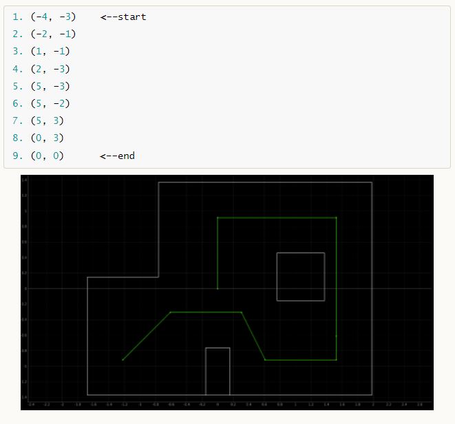
The primary objective of this lab is to enable the robot to navigate through a set of waypoints shown below. The lab is designed to be very open ended allowing experimenters to use several concepts discussed and implemented in the course such as open loop, closed loop, PID, mapping, localization, and off-board commands.
II. Materials/Software
- Fully Assembled Robot (Artemis, ToF Sensors, IMU, Motor Drivers)
- Jupyter Lab
III. Procedure/Design/Results
Overview
To enable the robot to effectively navigate through the set of waypoints shown above, I used closed loop feedback control (PID) for translations, closed loop feedback control (PID) for rotations. Below is the algorithm the robot follows to navigate through the map:
- Start at a point facing the 0 direction
- Use closed loop feedback control (PID) for rotation and rotate towards the next point
- Use closed loop feedback control (PID) for translation and move towards the next point
- Repeat the above steps until with the next point in the array until the last point is reached.
Implementation Selection
There are several possible ways of going about this lab. One can perform open loop control with timed commands, incorporate PID for turning and translations, or use localization at waypoints to determine your current and future locations. I felt that incorporating PID for turns and translations would be the best approach for this lab as our Lab 11 localization results were not very promising.
PID Translation Design
In this lab, a PID controller is implemented to handle translations and rotations. The control scheme operates by adjusting the output to meet a specified setpoint. Specifically, the controller outputs a PWM duty cycle to drive the motors. Through trial and error, it was determined that the translation controller is most effective with a KP value of 0.1 and a K_D value of 0.05.
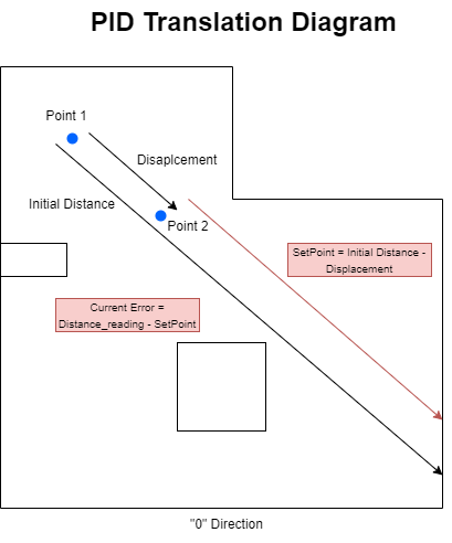
To initiate translation, the distance from the current position to the next point is calculated, and an initial Time-of-Flight (ToF) sensor reading is taken. This initial reading is used to determine the setpoint at that location, calculated as SetPoint = initial distance - displacement. Here, the displacement is the distance between the current and the next point the robot needs to travel. Below is a diagram illustrating the PID translation design and the associated software.

One of the challenges was obtaining an accurate distance measurement at the first point (-4, -3). The first point’s ToF readings were extremely inaccurate due to the long distance across the map and the slanted angle. Because of the inaccurate readings, the robot calculated an incorrect setpoint, causing the translation to fail.
void travelDistance(double distanceToTravel) {
    double previous_error_translation = 0;
    double integral_translation = 0;
    double Kp_translation = 0.1;
    double Ki_translation = 0.01;
    double Kd_translation = 0.05;
    unsigned long previous_time = millis();

    while (true) {
        distanceSensor.startRanging();
        double currentDistance = distanceSensor.getDistance();
        distanceSensor.clearInterrupt();
        distanceSensor.stopRanging();
        // double currentDistance = readDistanceFromToF();
        double remainingDistance = distanceToTravel - currentDistance;

        if (remainingDistance <= 0.0) {
            break;
        }

        unsigned long current_time = millis();
        double dt = (current_time - previous_time) / 1000.0;
        previous_time = current_time;

        double error_translation = remainingDistance;
        integral_translation += error_translation * dt;
        double derivative_translation = (error_translation - previous_error_translation) / dt;
        double output_translation = Kp_translation * error_translation + Ki_translation * integral_translation + Kd_translation * derivative_translation;
        previous_error_translation = error_translation;

        forward(output_translation);

        delay(10);
    }
}
PID Turn Design
To initiate a turn, the yaw angle is set to zero and the specified degree to rotate becomes the setpoint. The initial yaw angle and setpoint are used to guide the rotation process. The function continuously reads gyroscope data to update the current yaw angle, calculates the time difference (dt), and updates the yaw based on gyroscope readings. The PID controller then computes the error, integral, and derivative to determine the output rotation value. Depending on the sign of the output, it calls turn or turnRev to rotate the robot. The loop continues until the error is within a 2-degree threshold, ensuring precise rotation control. Below is the code for the same function:
void rotateByDegree(double relativeDegree) {
    double yaw_g = 0;
    double setpoint = yaw_g + relativeDegree;
    double previous_error = 0;
    double integral = 0;
    double Kp_rotation = 0.9;
    double Ki_rotation = 0.06;
    double Kd_rotation = 2;
    unsigned long previous_time = millis();

    while (true) {
        myICM.getAGMT();
        double gyro_data = myICM.gyrZ();
        // Serial.println(gyro_data);
        unsigned long current_time = millis();
        double dt = (current_time - previous_time) / 1000.0;
        previous_time = current_time;

        yaw_g += gyro_data * dt;
        double error = setpoint - yaw_g;
        integral += error * dt;
        double derivative = (error - previous_error) / dt;
        double output_rotation = Kp_rotation * error + Ki_rotation * integral + Kd_rotation * derivative;
        previous_error = error;
        Serial.println(output_rotation);
        if(output_rotation>=0)
          turn(output_rotation);
        else
          turnRev(output_rotation);
        // applyRotation(output_rotation);

        if (abs(error) < 2.0) {
            break;
        }

        delay(10);
    }
}
Issues Faced
There were several issues faced in this lab as this was the toughest lab of the course.
One prominent issue faced during this lab was the inaccuracy of the ToF sensor. Several times during a run, the ToF sensor would output wrong distance readings. This was discovered by tethering the robot and reading the distance values in the serial monitor. Due to this issue, the ToF readings from the first point were very inaccurate due to the long distance to the point across the map and the slanted angle. Because the inaccurate readings, the robot would calculate an inaccurate setpoint, causing the translation to fail.
Another major issue faced was the pre-caching of the ToF sensor. The ToF sensor outputted the distance value that was taken from the previous compilation. Eventually, I found that this happened because the distance sensor data was not ready and therefore it kept outputting previous values. To ensure the data would be ready, I used the following code which checks if the data is ready.
while (!distanceSensor.checkForDataReady() && cent.connected()){
      delay(1);    }
Although using closed loop controls, there were slight inaccuracy accumulation interms of direction and distance overtime which caused a lot of issue and was a major reason that I was not able to complete the entire maze at a go and without human interference. I was at max able to achieve 5-6 points.
Fails
Failed because of miscalculation of distance while coding.
Failed because of ToF malfunction.
Results
IV. Conclusion
The objective of this lab, to navigate the robot through the waypoints, was partially completed. This has been the most complex and time consuming lab in this course. I and my friends spent about 25-30 hours in the lab over a week trying to perfect the trajectory run. Even though faced many issues, the lab was very rewarding as it summated a lot of important concepts learned throughout the course. As always, the Professor and the TAs were very helpful and helped debug several issues.
Collaborators
Askari - I broke my ToF while testing out, so borrowed and worked with him on his hardware kit.
